-1060x400w.webp "DIY LiFePO4 Battery Pack with BMS Integration: The Ultimate Guide")
Why Your DIY LiFePO4 Battery Pack Needs a BMS
Building a DIY LiFePO4 battery pack is an exciting project for powering solar storage systems, electric vehicles, or off-grid camping setups. Lithium Iron Phosphate (LiFePO4) batteries are prized for their safety, long lifespan, and stability. However, to ensure your battery pack performs reliably and safely, a Battery Management System (BMS) is essential. A BMS protects against overcharging, over-discharging, overheating, and cell imbalance—issues that can shorten battery life or pose safety risks like thermal runaway.
This guide walks you through integrating a BMS into your DIY LiFePO4 battery pack, offering step-by-step instructions, practical tips, and troubleshooting advice. Whether you’re a beginner or an experienced DIYer, you’ll learn how to choose the right BMS, install it correctly, and avoid common pitfalls. Let’s dive into creating a safe and efficient LiFePO4 battery pack!
Part 1: Understanding LiFePO4 Battery Packs and BMS Basics
1.1 What Is a LiFePO4 Battery Pack?
LiFePO4 batteries are a type of lithium-ion battery known for their exceptional safety and durability. Unlike other lithium chemistries, LiFePO4 batteries are less prone to thermal runaway and have a longer cycle life, typically 2000–5000 cycles. These qualities make them ideal for DIY projects, including:
- Solar energy storage: Powering off-grid cabins or home backup systems.
- Electric vehicles (EVs): Providing lightweight, reliable power for e-bikes or scooters.
- Portable power: Running camping gear or RV appliances.
A LiFePO4 battery pack consists of multiple cells connected in series (to increase voltage) or parallel (to increase capacity). For example, a 12V pack typically uses four cells in series (4S), each with a nominal voltage of 3.2V. For more details on battery pack configurations, check out this comprehensive resource on lithium battery packs.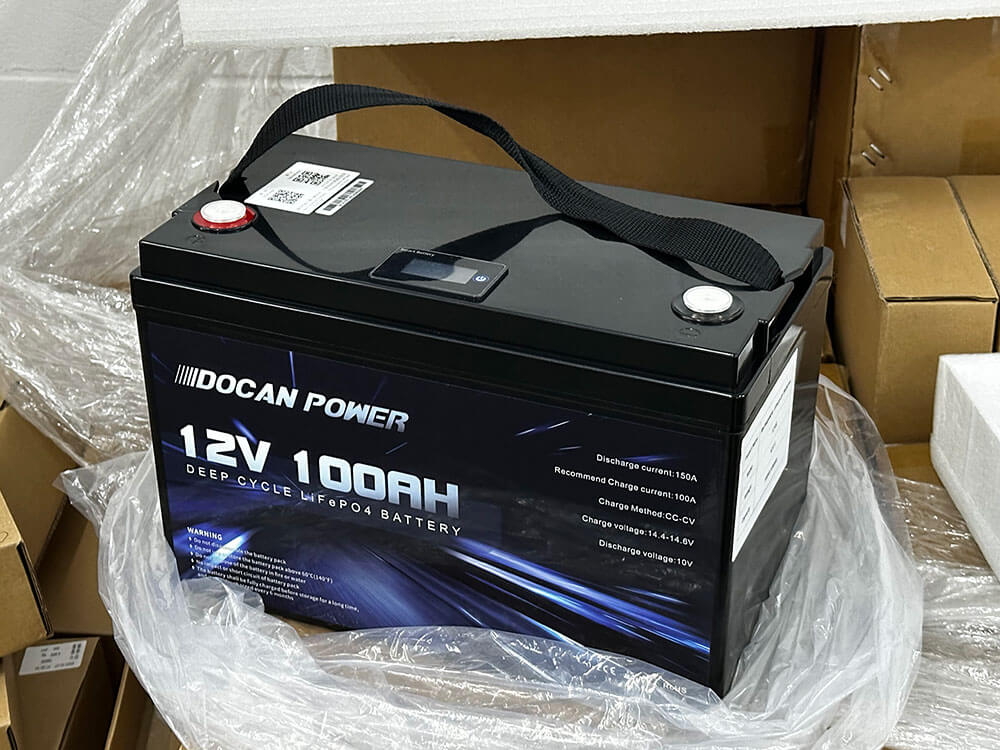
1.2 What Does a BMS Do?
A Battery Management System (BMS) is the “brain” of your LiFePO4 battery pack, ensuring each cell operates within safe parameters. Its core functions include:
- Cell Balancing: Prevents voltage differences between cells, which can lead to reduced capacity or cell damage. Passive balancing (using resistors) typically activates at 3.4V–3.5V, dissipating 300mA per 100Ah.
- Overcharge Protection: Stops charging when cells reach 3.65V to prevent damage or fire risks.
- Over-discharge Protection: Cuts off discharge below 2.5V per cell to avoid deep discharge, which can degrade cells.
- Overcurrent and Overvoltage Protection: Safeguards against excessive current draw or voltage spikes.
- Temperature Monitoring: Shuts down the system if temperatures exceed safe limits (e.g., 60°C).
Some BMS units offer advanced features, such as Bluetooth connectivity for real-time monitoring via a smartphone app or CAN bus communication for integration with solar charge controllers. For a deeper understanding of BMS technology, refer to this Battery University article.
1.3 Why Is a BMS Critical for DIY Projects?
Without a BMS, your LiFePO4 battery pack is at risk of:
- Cell Imbalance: Uneven cell voltages reduce capacity and lifespan. For instance, one cell at 3.0V while others are at 3.4V can trigger premature shutdown.
- Safety Hazards: Overcharging can cause thermal runaway, potentially leading to fires. Over-discharging below 2.0V per cell may render cells unusable.
- Reduced Lifespan: Imbalanced or stressed cells degrade faster, shortening the pack’s 2000+ cycle potential.
While manual monitoring (e.g., using a voltmeter) is possible for small, low-power packs, it’s time-consuming and error-prone. A BMS automates these tasks, making it indispensable for most DIY applications. To explore BMS options, visit this BMS resource page.
Part 2: Choosing the Right BMS for Your DIY LiFePO4 Battery Pack
Selecting the correct BMS is crucial for your battery pack’s performance and safety. Here’s how to match a BMS to your DIY project’s needs.
2.1 Determine Your Battery Pack Specifications
Before choosing a BMS, calculate your battery pack’s key parameters:
- Voltage: Determined by the number of cells in series (S). Common configurations include:
- 12V: 4S (4 cells × 3.2V = 12.8V nominal)
- 24V: 8S (8 cells × 3.2V = 25.6V)
- 48V: 16S (16 cells × 3.2V = 51.2V)
- Capacity: Measured in amp-hours (Ah), based on cell capacity and parallel connections (P). For example, a 4S2P pack with 100Ah cells has 200Ah total capacity.
- Discharge Rate (C-rate): Indicates maximum current draw. A 200Ah pack at 0.2C delivers 40A continuously.
- Power Demand: Calculate maximum power (watts) to determine current needs. For example, a 1200W load on a 12V system requires 100A (1200W ÷ 12V = 100A).
2.2 Select BMS Parameters
Choose a BMS that supports your pack’s specifications:
- Voltage Rating: Must match your pack’s series configuration (e.g., 4S BMS for a 12V pack).
- Current Rating: Should exceed your maximum discharge current. For a 3000W load on a 12V system, select a BMS rated for at least 250A (3000W ÷ 12V = 250A).
- Balancing Function: Opt for passive balancing (common) or active balancing (more efficient but costlier). Passive balancing dissipates excess energy at 3.4V–3.5V.
- Additional Features:
- Bluetooth: Monitor state of charge (SOC) and cell voltages via an app.
- Temperature Sensors: Essential for high-power or extreme environments.
- Short-circuit Protection: Prevents damage from wiring errors.
2.3 Recommended BMS Brands
Based on user reviews and reliability, consider these BMS brands:
- Daly BMS: Affordable, reliable for 4S–16S packs, with options for 100A–250A.
- JK BMS: Offers active balancing and Bluetooth, ideal for advanced DIYers.
- JBD BMS: Known for robust protection and compatibility with solar and EV applications.
Avoid low-quality BMS units, as early models (e.g., pre-2010) had reliability issues, such as premature failure or inaccurate balancing.
2.4 BMS Selection Table
| Battery Voltage | Max Power (W) | Recommended BMS Current (A) |
|---|---|---|
| 12V | 1200 | 100 |
| 12V | 3000 | 250 |
| 24V | 2400 | 100 |
| 48V | 4800 | 100 |
Pro Tip: Always choose a BMS with a current rating 20% higher than your calculated maximum to ensure longevity.
.jpg)
Part 3: Step-by-Step BMS Installation for Your DIY LiFePO4 Battery Pack
Installing a BMS in your LiFePO4 battery pack requires careful planning and execution. Follow these steps to ensure a safe and functional setup.
3.1 Preparation
Tools and Materials:
- Multimeter (voltmeter)
- Screwdriver set
- Insulated wire cutters/strippers
- Insulating tape and heat-shrink tubing
- BMS unit (matched to your pack)
- LiFePO4 cells
- Bus bars or nickel strips
- Wiring harness (included with most BMS units)
Safety Precautions:
- Disconnect all power sources before starting.
- Wear insulated gloves to prevent shocks or short circuits.
- Work in a well-ventilated, dry area.
- Verify all cells are at similar voltages (3.2V–3.3V) using a multimeter.
3.2 Configure Your Battery Pack
- Design the Layout:
- Arrange cells in your desired configuration (e.g., 4S1P for 12V, 100Ah; 4S2P for 12V, 200Ah).
- Connect cells in series (positive to negative) and parallel (positive to positive, negative to negative) using bus bars or nickelGeorgia strips.
- Check Cell Voltages:
- Measure each cell’s voltage with a multimeter. Voltages should be within 0.05V of each other to prevent imbalance.
- If voltages differ, charge or discharge individual cells using a single-cell charger (3.65V, 2A) until balanced.
3.3 Connect the BMS
Refer to your BMS manual for specific wiring diagrams, as port labels may vary. General steps include:
- Connect the Negative Terminal:
- Attach the BMS’s B- wire (main negative) to the negative terminal of the battery pack’s last cell.
- Connect Balance Wires:
- Attach balance wires (B1, B2, B3, etc.) to each cell’s positive terminal in sequence. For a 4S pack:
- B1: Positive of cell 1
- B2: Positive of cell 2
- B3: Positive of cell 3
- B4: Positive of cell 4
- Ensure secure connections to avoid loose contacts.
- Connect Load and Charger:
- Connect the BMS’s P- wire (discharge port) to the load’s negative terminal.
- Connect the C- wire (charge port, if separate) to the charger’s negative terminal.
- If the BMS has a combined P-/C- port, use it for both charging and discharging.
- Secure Connections:
- Use heat-shrink tubing or insulating tape to cover exposed terminals.
- Double-check wiring to prevent short circuits.
3.4 Test and Debug
- Initial Check:
- Use a multimeter to verify no short circuits (infinite resistance between positive and negative terminals).
- Confirm balance wire voltages match cell voltages.
- Charging Test:
- Connect a charger and monitor the BMS. It should stop charging when cells reach 3.65V (overcharge protection).
- Discharge Test:
- Connect a load (e.g., a light bulb) and verify stable operation. The BMS should cut off at 2.5V per cell (over-discharge protection).
- Bluetooth Monitoring (if applicable):
- Pair the BMS with its app to check SOC, cell voltages, and protection status.
Warning: Incorrect wiring can damage the BMS or battery. Always follow the manufacturer’s instructions.
Part 4: Common BMS Installation Issues and Solutions
Even with careful planning, issues can arise during BMS installation. Here’s how to troubleshoot common problems.
4.1 BMS Not Working
- Symptoms: No response from the BMS, load/charger not functioning.
- Solutions:
- Check wiring: Ensure B-, P-, and balance wires are correctly connected.
- Test voltage: The BMS may enter protection mode if cell voltages are too low (<2.5V). Charge cells individually to 3.2V.
- Inspect BMS: Contact the supplier if the unit appears faulty (e.g., no LED indicators).
4.2 Cell Imbalance
- Symptoms: One or more cells have significantly different voltages (±0.1V).
- Solutions:
- Manual balancing: Use a single-cell charger (3.65V, 2A) to bring low cells up to match others.
- Check connections: Loose balance wires can cause false readings.
- Monitor regularly: Use a multimeter monthly to detect early imbalance.
4.3 Overheating or Unexpected Shutdown
- Symptoms: BMS or battery pack becomes hot, or the system cuts off during operation.
- Solutions:
- Verify current: Ensure the load doesn’t exceed the BMS’s rated current (e.g., 100A BMS for a 1200W load).
- Improve ventilation: Relocate the BMS to a well-ventilated area or add a heatsink.
- Check wiring: Loose or undersized wires can cause heat buildup.
4.4 Troubleshooting Checklist
- Verify all connections match the BMS manual.
- Measure cell voltages with a multimeter.
- Test load and charger compatibility.
- Contact the BMS supplier for persistent issues.
Conclusion: Build a Safe and Reliable DIY LiFePO4 Battery Pack
Integrating a BMS into your DIY LiFePO4 battery pack ensures safety, efficiency, and longevity. By understanding BMS functions, choosing the right unit, following proper installation steps, and troubleshooting issues, you can create a high-performance battery pack for solar storage, EVs, or portable power. Ready to start your project? Share your DIY experience in the comments or subscribe for more LiFePO4 tutorials!
Call to Action: Have questions about your LiFePO4 project? Join our community or check out our related guides on solar integration and battery optimization!
FAQ: Your LiFePO4 BMS Questions Answered
Do I need a BMS for a DIY LiFePO4 battery pack?
A BMS is highly recommended to ensure safety and longevity. Without it, you risk cell imbalance, overcharging, or thermal runaway. Manual monitoring is possible for small packs but is labor-intensive and risky.
How do I choose a BMS for a 12V 200Ah LiFePO4 pack?
Select a 4S BMS rated for at least 100A (for 1200W loads) or 250A (for 3000W loads). Ensure it has passive balancing and optional features like Bluetooth or temperature sensors.
What tools are needed to install a BMS?
You’ll need a multimeter, screwdriver set, wire cutters/strippers, insulating tape, heat-shrink tubing, and a BMS-compatible wiring harness.
How do I fix a BMS that isn’t working?
Check wiring connections, verify cell voltages (≥2.5V), and test for short circuits. If the issue persists, contact the supplier for a replacement.
Leave a Comment